A Rotary Unwinder works by supporting a wound roll of web material on a rotating shaft or chuck, then actively controlling the speed and braking torque applied to that shaft as the downstream process pulls material off the roll. The core principle is continuous tension control: as the roll diameter decreases during unwinding, the same linear web speed requires progressively less rotational torque, and the unwinder's control system compensates automatically to maintain a stable, consistent web tension throughout the roll's life. Yitong Environmental Technology describes this function clearly: a rotary unwinder continuously feeds a roll of material into a downstream converting, printing, coating, or laminating process at a controlled speed and tension, rotating the parent roll as material is consumed and maintaining a steady web feed without interruption (Source: Yitong Environmental Technology, What Is a Rotary Unwinder). Tension accuracy matters because inconsistent tension causes wrinkles, breaks, registration errors, and print defects that cost time and material to correct.
To understand how a rotary unwinder works, it helps to understand the problem it exists to solve. Web-based manufacturing processes, including printing, slitting, coating, laminating, and flexible packaging converting, all require a continuous, stable-tension flow of material entering the machine at a consistent speed. The raw material arrives as a wound roll, and a wound roll presents a fundamental mechanical challenge: as material is consumed from the outside of the roll inward, the roll diameter decreases continuously. At constant shaft speed, a smaller diameter roll delivers less web per revolution. At constant tension with a simple braking system, the tension increases as diameter decreases because the same brake torque now acts on a smaller moment arm.
Jota Machinery explains this directly: an unwind stand is far more than a mechanical holder; it is a carefully engineered system designed to support heavy jumbo rolls, control tension as the roll diameter decreases, and keep the web aligned as it enters downstream sections, with proper design preventing wrinkles, breaks, and uneven edges that cost hours of downtime and product consistency (Source: Jota Machinery, What Is an Unwind Stand). A rotary unwinder addresses this decreasing-diameter problem through either a diameter-sensing control loop, a dancer roller feedback system, or a load cell tension measurement system, each continuously adjusting the unwinding torque to compensate for the changing roll geometry.
A rotary unwinder integrates several mechanical and control subsystems, each performing a specific function in the web handling sequence.
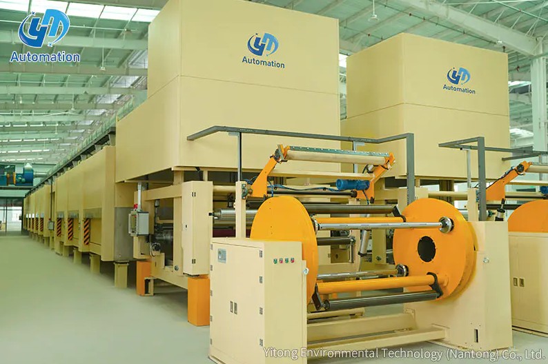
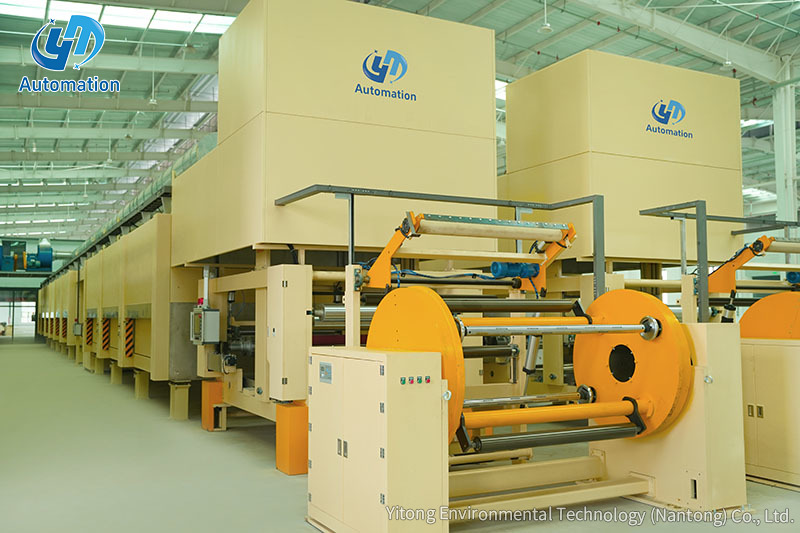
The main frame provides the structural foundation that supports the parent roll's weight and resists the dynamic forces generated during web pulling, acceleration, and deceleration. Roll support takes one of two main forms: a shafted design where a mandrel shaft is threaded through the roll core and locked into side-mounted bearings, or a shaftless design where hydraulic or mechanical chucks expand into the roll core from each end without requiring a full-length shaft. Jota Machinery notes that shaftless turret systems are used for flexible packaging films to ensure smooth handling of stretchable materials, while shaft-based designs are more common for rigid film, paper, and foil applications where core retention is less of a concern (Source: Jota Machinery, What Is an Unwind Stand). Paper parent rolls can weigh several tonnes and exceed 2,500mm in diameter, requiring heavy-duty frame construction and high-torque tension control to handle safely (Source: Yitong Environmental Technology, What Is a Rotary Unwinder).
The braking or drive system is what physically controls the rotation of the roll shaft in response to the web pull applied by the downstream machine. Three main actuation technologies are used.
In pneumatic brake systems, air pressure applied to a disc or drum brake on the unwind shaft creates the braking torque that resists the pull of the downstream process. A basic mechanical approach uses pneumatics or springs to balance the force of a rotating dancer or rotary web festoon against a brake on the unwind shaft, as described by Label and Narrow Web in a technical overview of converting equipment configurations (Source: Label and Narrow Web, Rewinds, Unwinds and Splicers). The air pressure is modulated by the tension controller in real time to compensate for the decreasing roll diameter.
In magnetic powder brake systems, electrical current through a powder-filled coupling generates the braking torque, with torque output proportional to the applied current. This allows very smooth, electronically precise torque modulation without the hysteresis effects that can affect mechanical brakes.
In driven unwinder configurations, a regenerative motor actively controls shaft speed rather than just applying braking resistance. This allows the unwinder to handle high-inertia large-diameter rolls more precisely during acceleration and deceleration, and to participate in tension control by varying motor speed in response to dancer position or load cell feedback signals.
The dancer roller is the component that most directly maintains continuous tension control between the unwinder and the downstream process. A dancer roll is a free-floating roller that rests on the web between the unwind shaft and the first fixed nip or guide roller downstream. Montalvo Corporation describes the principle: all dancer tension controls have idler rolls or arms that are preloaded for one direction, and as a web is drawn over a dancer roll it moves in response to any changes in its position, with movement reflecting a change in web tension, and a sensor monitoring that position to control the drive's movement (Source: Montalvo Corporation, Dancer Roll Tension Control Basics).
The dancer roller acts as a mechanical buffer and sensor simultaneously. When the downstream process pulls more web than the unwinder is delivering, the dancer drops, and the control system responds by reducing braking torque or increasing motor speed to restore supply. When supply exceeds demand, the dancer rises, and the system applies more braking or reduces speed. Yitong Environmental Technology reports that load cell systems, where force transducers measure actual web tension at a fixed roller, achieve tension control accuracy of plus or minus 1 to 3 percent of set point under stable operating conditions (Source: Yitong Environmental Technology, What Is a Rotary Unwinder).
Even a well-wound roll will exhibit some lateral web wander as the roll unwinds due to edge variation, core telescoping, or material width inconsistency across the roll width. A web guide system corrects this by sensing the web edge or centreline position and repositioning either the unwind stand or a steering roller to keep the web centred as it enters the downstream process. Without web guiding, lateral drift in the web would cause misalignment in printing registration, uneven slitting cuts, and coating coverage problems across the web width.
The most technically demanding aspect of rotary unwinder operation is maintaining constant web tension from a full roll to a nearly empty core, since the roll geometry changes continuously and the correct braking torque changes with it.
Web tension in Newtons or pounds force is determined by the relationship between the braking torque applied to the unwind shaft and the current roll radius. As the roll decreases in diameter, the same web tension requires progressively less braking torque, following the relationship: tension equals torque divided by radius. A control system that holds braking torque constant as the roll decreases in diameter will progressively overtension the web, eventually causing web breaks. A system that correctly reduces torque proportionally as the diameter decreases maintains constant tension through the full roll life.
The control system needs to know the current roll diameter to calculate the correct torque command at any moment. Three approaches are used in practice. Ultrasonic or laser diameter sensors measure the roll diameter directly in real time and feed this value to the tension controller. Rotary encoder-based calculation uses the relationship between shaft revolutions and web speed, measured at a downstream tachometer roll, to calculate roll diameter mathematically without a direct measurement. Dancer position integration uses the dancer roller's position history over time to track consumed material and infer current diameter.
Mitsubishi Electric's tension control engineering reference identifies these as the main categories of tension control methods, classifying them as manual, open-loop reel diameter detection, and closed-loop tension feedback, with the closed-loop feedback approach providing the best accuracy for high-speed converting applications (Source: Mitsubishi Electric, Factory Automation Tension Control Complete Guide).
A rotary unwinder does not control tension for the entire production line. It controls the tension in the unwind zone, which Montalvo Corporation defines as the zone between the unwind drive and the first master drive downstream (Source: Montalvo Corporation, Dancer Roll Tension Control Basics). Downstream processing zones and rewind zones each have their own tension control loops. The unwinder's job is to provide a consistently tensioned web entering that first downstream nip, at which point tension control passes to the next zone's control system.
In high-volume converting operations, stopping the production line each time a roll of material runs out is a significant source of waste and productivity loss. Bringing a press back into register and up to speed after a stop consumes material and time, and the scrap generated during restart adds directly to production cost. An automated splicing system on the rotary unwinder eliminates these stops by joining the tail of the expiring roll to the leading edge of a new roll while the line continues running at production speed.
Paper, Film and Foil Converter describes the best practices for this process: tracking the location of the splice from unwind to winder as it progresses through converting stages, employing a core detect feature to minimize residual web on the expiring roll, simplifying splice preparation to ensure consistent splice position, and using paster roll technology with an electro-mechanical firing mechanism to minimize paster bounce and promote accurate contact with the product roll (Source: Paper Film and Foil Converter, Efficiency in Winding and Unwinding). When executed correctly, an automatic splice is essentially invisible to the downstream process because the dancer roller absorbs the brief tension transient during the splice event.
Rotary unwinders appear wherever a wound roll of material is the input to a continuous production process.
Matching a rotary unwinder's specifications to the application requirements determines whether it delivers consistent, trouble-free operation or becomes a source of ongoing tension variability and downtime.
| Specification | What It Determines | Typical Range |
| Maximum roll diameter | Largest roll the frame can accommodate | 300mm to 2,500mm or more |
| Maximum roll weight | Structural load limit of the frame and bearings | 50kg to several tonnes |
| Maximum web width | Widest roll the shaft and frame will accept | 50mm to 3,500mm or more |
| Tension control range | Minimum and maximum tension the system can maintain stably | Application-dependent |
| Maximum line speed | Fastest web speed the tension control can track accurately | Up to 600m/min for high-speed lines |
| Tension control method | How tension feedback is measured and controlled | Dancer, load cell, or diameter-based |
The Ytinte Rotary Unwinder is designed to address the full range of these specification requirements across paper, film, foil, and nonwoven applications, combining precise tension control with robust frame construction and web guiding to deliver consistent, stable web feed into downstream converting and printing processes.
Lépjen kapcsolatba velünk
Ajánlott termékek
Lépjünk be
Érintés
A Yitong Environmental Technology (Nantong) Co., Ltd. impregnáló berendezésekre szakosodott gyártó.


Lépjen kapcsolatba velünk
Phone: +86-19555016088
Email: [email protected]
Add:A Haiyan úttól délre, a Nanhai úttól nyugatra, a Tongzhou-öböl Jangce folyó-tenger közös fejlesztési demonstrációs övezete, Jiangsu, Kína